Table of Contents
What is Optical Fiber Cable?
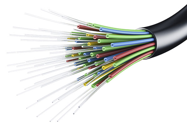
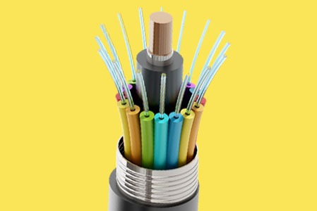
Optical fiber cables are made from concentric layers of glass. Each layer of glass has a slightly different index of refraction or density. The center rod is called the core, and the outer layers are called the clad. The core is a very thin strand of highly refined cylindrical glass. Approximately, 20 miles of a 0.010-inch diameter core can be drawn from a 4.5-inch cube of glass.
 |
| What is Optical Fiber |
A cable’s glass core may have a diameter of 4.5 microns (0.0002 inch) or may be as large as 400 microns (0.016 inch). The clad is fused directly to the core. The naked eye cannot see the difference between the two materials. However, the clad has a different optical density than core material. Both core and clad may be made of glass or plastic materials of different densities, or core may be glass and the clad plastic.
Optical fiber cable work on the theory of reflection. That reflection results at the interface between two materials of different densities. For instance, in a metallic waveguide the radio frequency energy is reflected along the guide when one-half wavelength of energy is shorter than the width of the waveguide.
However, in fiber optics, the energy is reflected down the glass waveguide when the angle of reflection remains smaller than a critical angle. The critical angle is determined by the ratio of the densities of the core and clad materials.
The diameter of the core is 50 microns whereas the clad adds another 50 microns to the overall diameter. Keep in mind that the core is only 0.002 inch in diameter. When light approaches the fiber core at an angle greater than the critical angle theta (q), away from the centerline of the core, then the core-clad interlace will not reflect the light back into the core area.
The light will pass through the clad. Light passing through the clad is dissipated into the air outside the light cable. Important to the proper operation of fiber optic cables is the acceptance cone, which is formed.
Any approaching light coming near the cable from any direction at an angle of 40° or less from the centerline of the cable will move down the core of the cable. A cone is formed by a boundary of 40° from the centerline in all directions. All light arriving at the core within the acceptance cone will enter the core and pass through the light guide.
What is Optical Fiber Cable Connector?
Fiber optic connectors are important inasmuch as they serve as a means of splicing the fiber and causing it to continue the light beam with minimum of light (signal) loss. See Figure 11-10. Properly treated fiber ends are essential to a good installation. Figure 11-11 shows how the connectors are treated and how the fiber is polished with the proper equipment.
 |
| Optical Fiber Cable |
Cable Trays
Plastic innerduct commonly used for underground or outside plant construction may not have the appropriate fire safety characteristics required for optical fiber cable wiring in buildings. One reason for cable trays and raceways is to prevent the accumulation of wires and cables in front of electrical equipment located behind normally accessible panels.
Cables should be supported by the building structure such that the cable will not be damaged by normal building use. The installation of optical fiber cable should be done neatly and in a workmanlike manner.
Optical Fiber Cable Tools
If you are looking for tools to work with fiber optics, the following is a listing of the specialized hand tools designed to work with this type of material. They have a tendency to eliminate most of the common defects produced by those not adequately skilled in making splices or installations.
There are a number of hand tools available for fiber optic cabling needs. There is a wide variety of tools for optical fiber termination, including strippers, tweezers, scribes, cleavers, and microscopes, polishing supplies, safety kits, and more.
Strippers for fiber optic are accurate to −0 mm, +0.0127 mm with no adjustment necessary. It has back-up blades that support the cutting blades, nest positively, and “lock up” when the tool is closed. This maintains a perfect concentricity. The buffer being removed acts as a guide and provides protection for the fiber. Strippers also are available in a three-piece kit in the most popular sizes, 203 microns (red handles), 245 microns, light blue handles,
and 305 microns with white handles.
The color-coded handles aid in quick identification. They come in a vinyl case that provides storage and protection. The fiber optic cleaver is designed for use with mechanical splices, with the newer “no-polish connections” and any other cleaves that require precise cleave lengths. It works well with 125-micron nominal cladding diameters and accommodates fibers in coated as well as cable form.
It has a carbide-cleaving blade good for at least 5000 consistent cleaves. The cleave length is adjustable from 6.5 mm to 20 mm/0.25 inches to 0.75 inches. The cleave angle is <1 all=”” and=”” cleaves.=”” cleaves=”” font=”” nbsp=”” of=””>
This optical fiber cable stripper has a 1.0-mm diameter-stripping hole at the tip of the tool so it can be used to strip the fiber jacket; and a 140-μm-diameter hole with a V-opening in the blade allows removal of 250-micron buffer coating from 125-micron fiber.
This is preset at the factory with no adjustment needed. It will not scratch or nick the glass fiber. The fiber optic jacket stripper removes the outside jacket from the optical fiber cable. The stripper has two stripping notches: one with a cutting diameter of 1.25 mm and the other with a cutting diameter of 1.5 mm, and can be used on 2.0-mm and 3.00-mm cable. The 1.5-mm notch works especially well on loose tube cable. It is easy to use and always leaves a clean strip.
The Kevlar shears has a nonslip serrated blade on each model and provides the solution for trimming back the DuPont Kevlar that serves as the central strength member in the optical fiber. The shears are made of hot-forged, high-carbon steel for longer life. The tool has a quick action spring release so the tool is ready when you are. The high leverage provides powerful cutting action.
The fiber optic inspection microscope has three built-in magnifications: 150x, 175x, and 200x. The universal adapter accepts most ST, SC, and FC 2.5 mm connector ferrules. It has an on/off switch, bulb rotation knob, and a focus wheel that is designed with a firm control dial to hold the focus. The eyepiece is so designed that it is unnecessary to remove conventional eyeglasses for safety eyewear.
There are various kits available for those working with fiber optics. These include the polishing kit and the fiber-safe safety kit:
The fiber-safe safety kit includes:
Polishing/work matt:
The vinyl black work mat serves a dual purpose (14 inches × 22 inches). Its primary function is to allow you to easily see the fiber scraps instead of trying to find them on a lighter colored work surface. It can also serve as a subsurface for some polishing applications. Instead of using a hard, non giving surface, you have a resilient matt that depresses easily and allows you to quickly pick up the fibers you are working on.
Fiber scraps trash can:
The disposable fiber scraps trashcan gives you the safest method of disposing of glass fiber scraps because it can be incinerated when full. Splinter removal tweezers: The splinter removal tweezers Teflon coating provides the cushioning you need to remove glass fibers splinters without shattering or breaking the glass.
Bifurcated cleaning swipes: The bifurcated (two-pronged) swipes put an end to working with messy bottles of alcohol and hand wipes to clean fiber ends before splicing, cleaving, or terminating fiber. The tube contains 99% isopropyl alcohol. Hand pressure breaks the seal, and the alcohol is dispensed only when you squeeze the tube, reducing evaporation and alcohol waste.
Safety glasses: They should always be worn when working with fiber. They have a single lens wrap-around feature to provide additional safety and the latest technology in safety glasses. The spring-loaded adjustable, automatic impact punch down tool is used for terminating wires on 110/88 or 66-type connecting blocks. Precision hardened and interchangeable blades spread the termination prongs to allow fast and easy insertion of the wire into the contact, providing a tight termination that resists corrosion. The blade finishes the job in the same motion by neatly cutting off excess wire.
The rotary cable strippers are available for cable stripping the easy way. One stripper can strip cable with outer diameter of 8 mm to approximately 35 mm. The other strips cable with other diameter of 4 mm to approximately 25 mm. Replacement blades are available.
Wire strippers and cutters strip and cut commonly used wire, single or stranded, AWG or metric. Each tool will strip several different wire sizes. The plier-nose is an extra feature along with custom grips and a spring release. The hardened pivoted joint produces a tool with a longer life. Good tools to have on the solder bench or in an assembly area. Other tools and devices that make the job easier and more efficient.
DLC Cable Entries
In a conventional digital loop carrier (DLC) optical fiber cable entry method, there can be problems. The cable is drawn into the closure, and then is grounded and exposed inside the case. The buffer tubes are attached to a splice tray inside the closure, and pigtails are spliced to the fibers contained in the buffer tube.
Disadvantages of this configuration are:
• If the DLC is at a junction splice, rather than at the end of a branch splice, several cables must be brought in, prepped, and spliced inside the box. This is sometimes difficult to accomplish, particularly if the copper splices have already been made.
• If the DLC is at a junction splice, sometimes the cables are brought into a hand hole, then a length of cable is brought into the box, prepped, and pigtails are spliced onto the end of the extension cable. This creates another splice in the path, and still has the disadvantage of the inside preparation.
• In both instances, and at the end of a branch splice, a preparation of the cable inside the box means that a tent must be set up to prep the splice operation, and the fusion-splice must be made outside, rather than an arrangement that allows the splicing to be done inside a splicing trailer or van. Outside splicing is particularly difficult if the DLC is in a hard-to-reach area, such as on the side of a hill or off the road, where a level area to set a splicing table is difficult to find.
• When the cables are prepped inside the box, the fragile buffer tubes occupy space with the copper splices and power supply hookups. If attention is not paid to the clearance between the buffer tubing and the other activities, damage to the fiber patch will result.
• If the DLC must be replaced due to damage or vandalism, the splicing inside the DLC to be replaced must be cutoff and redone inside the new unit, increasing down time.
Some of the definitions you may want to put in your thinking space and use later. Digital loop carrier (DLC). This is used to provide two dial tones over a single twisted copper pair. It is not always a good idea for use with fax machines and modems. Open shortest path first (OSPF). This is a standard traffic control program used on routers. It was developed in 1970s for use with Internet applications.
Final Word
Hope you understand this article about Optical Fiber Cable. Incase of any doubt please comment below. Subscribe our website to get every new post update to your email. Please follow our website – ElectricianWorld.net for future updates. Thank you for visiting our website.


