In this article we are going to see about 12 different types of transformers used in the energy distribution. Transformer is a electrical device which is used to convert electrical energy of higher voltage to a lower voltage without changes in frequency before and after the voltage transformation. It is mostly used in distribution lines of urban areas.
They are Step-down, step-up, isolation, variable, current, power, potential, auto, single phase, three phase, air core and the iron core transformer. Where are they used, principle, construction, operation and losses are properly described in below.
Table of Contents
What is Transformer?
Electrical definition: It is a electrical equipment which is used to convert electrical energy of higher voltage (usually 11kV-22kV-33kV) to a lower voltage (230V or 440V) without changes in frequency before and after the voltage transformation.
Its main application is mainly within sub-urban areas, public supply and industrial consumers. With given secondary voltage, distribution transformer is usually the last in the chain of electrical energy supply to households and industrial’s.
Principle
A transformer consists of two conductors called the primary winding and secondary winding, and a steel core that magnetically links them together. These two winding’s can be considered as a pair of mutually coupled coils. At the instant a primary winding is energized with AC(Alternating Current), a flow of electrons begins. During the instant of switch closing, buildup of current and magnetic field occurs.
As current begins the positive portion of the sine wave, lines of magnetic force develop outward from the coil and continue to expand until the current is at its positive peak. The magnetic field is also at its positive peak. The current sine wave then begins to decrease, crosses zero, and goes negative until it reaches its negative peak. The magnetic flux switches direction and also reaches its peak in the opposite direction.
DC(Direct current) is not transformed, as DC does not vary its magnetic fields. It is usually consists of two insulated winding’s on a common steel core – with an alternating current power circuit, the current changes continually 60 times per second, which is standard in the United States. That means circuit frequency in USA is 60 hertz. Other countries may use other frequencies.
In Europe, 50 cycles per second is common. In India 50 Hz. Strength of a magnetic field depends on the amount of current and number of turns in the winding. When current is reduced, the magnetic field shrinks. When the current is switched off, the magnetic field collapses.
Construction of Transformers
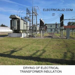
There is no internal moving parts in transformers, and it transfers energy from one circuit to another by electromagnetic induction method. External cooling may include heat ex changers, radiators, fans, and oil pumps. Radiators and fans are evident in figure. The large size tank at the top is a conservator.
 |
| Construction |
They are typically used because a change in voltage is needed everywhere. Power transformers are defined as transformers rated 500 kVA and larger. Larger types are oil-filled for insulation and cooling. The rating smaller than 500 kVA are generally called distribution TFS.
If the secondary coil has twice as many turns as the primary, it will be cut twice as many times by the flux, and twice the applied primary voltage will be induced in the secondary coil. The total induced voltage in each winding is proportional to the number of turns in that winding.
E1 – Primary voltage.
I1 – Primary current.
E2 – Secondary voltage.
I2 – Secondary current.
N1 – Primary turns and
N2 – Secondary turns.
Formula is,
E1/E2 = N1/N2 = I2/I1
The current is inversely proportional to both voltage(Primary and secondary) and number of turns. This means that if voltage is stepped up, the current must be stepped down and vice versa. The number of turns(N) remains constant unless there is a tap changer. The power output or input of a TF equals volts times amperes. If the small amount of loss is disregarded, input equals to output.
E1 x I1 = E2 x I2
Types of Transformers Classified by Application
1. Power level (From fraction of a watt to many megawatts),
2. Application (Power supply, impedance matching, circuit isolation),
3. Frequency range (Power, audio, RF)
4. Voltage range (A few volts to about 750 kilo volts)
5. Cooling type (Air cooled, oil filled, fan cooled, water cooled, etc.)
6. Purpose of using (Rectifier, arc furnace, amplifier output, etc.)
7. Number of turns in the coils.
Step Down Transformers
It is designed to reduce voltage from primary to secondary. If there are fewer turns in the secondary winding than in the primary winding, the secondary voltage will be lower than the primary voltage is called step down TFS. It is used to down the voltage output for commercial usage. If 33kV, 22kV or 11kV is the primary voltage that we gives can get 230V or 440V in the secondary coil is step down.
 |
| Step Down |
Step Up Transformers
It is designed to increase voltage from primary to secondary. If there are fewer turns in the primary winding than in the secondary winding, the secondary voltage will be higher than the primary voltage is called step up TF. If we set up primary coil has few winding less than secondary can get higher voltage output in the secondary winding.
 |
| Step Up |
Isolation Transformers
When the primary winding and the secondary winding have the same amount of turns there is no change in voltage and the ratio of coil turns also unity is called isolation transformer.
Variable Transformers
The primary coil and secondary coil have an adjustable number of turns which can be selected without reconnecting is called the variable TF. The primary winding, which receives the energy and it is not always the high voltage winding.
Current Transformers
These types are used in electric metering for large load needed condition to reduce the current range or level presented to the metering circuit in order to make it more manageable and safe. A current transformer is a type of ‘instrument TF’ that is designed to provide a current in its secondary winding which is accurately proportional to the current flowing in its primary winding.
Power Transformers
The types are selected based on the application, with the emphasis toward custom design being more apparent the larger the unit. It is available for step-up operation, primarily used at the generator and referred to as generator step-up TF, and for step-down operation, mainly used to feed distribution circuits. This types are available as single-phase or three-phase apparatus.
The power TF construction depends upon the application. This type intended for indoor use are primarily of the dry type but can also be liquid immersed. For outdoor use, types are usually liquid immersed.
Application: 1. Step-up operation – Generator step-up.
2. Step-down operation – Distribution circuits.
Potential Transformers
It is a special type of TF that allows meters to take readings from electrical service connections with higher voltage than the meter is normally capable of handling without at potential TF. The types are used with voltmeters, watt-meters, watt-hour meters, power-factor meters, frequency meters, synchro scopes and synchronizing apparatus, protective and relays, and circuit breakers.
Single TF can be used for a number of instruments if the total current required by the instruments connected to the secondary winding does not exceed the KVA rating.
Auto-Transformers
It is possible to obtain transformer action by means of a single coil, provided that there is a tap connection somewhere along the winding. Transformer having single winding are called auto-transformers. It has the usual magnetic core but single winding, which is common to both the primary and secondary circuits. The primary is always the portion of the winding connected to the AC power source.
This type may be used to step up or step down. If the primary is the total winding and is connected to a supply, and the secondary circuit is connected across only a portion of the winding, the secondary voltage is step down.
Single Phase Transformers
The type has two winding’s, one is primary and another one is secondary. It is mostly used in low voltage applications as electronic devices. The type operate as a step down TF and decrease the commercial voltage value to the suitable value for the used electronics supplying. Secondary side in the electronic devices, rectifier is connected to convert AC voltage to the DC voltage.
Three Phase (3 Phase) Transformers
Three single phase units connected in the three phase system is called three phase transformer. The type is commonly used in the industries and plants for transmission and distribution.
Air Core Transformers
If an AC is supplied to a coil, a magnetic field is produced surrounding it. If another coil is brought this magnetic field, EMF is induced across the second coil also as per Faraday’s law. This induced EMF in the second coil can be utilized to a load. As in this method the flux is linked with both coils through air. This arrangement is called air core TF
Iron Core Transformers
Primary and secondary winding’s are wound on multiple iron plate which provide a path to the generated flux. These types are widely used TFS in which the efficiency is high compared to the air core type.
Transformer Construction
There are three main parts in the distribution TF,
1.Winding 2.Magnetic core 3.Tank.
Winding
Where incoming(primary side) alternating current generates magnetic flux, which in turn induces a voltage in the secondary winding.
Magnetic Core
The Material allowing transfer of magnetic field generated by primary coil to secondary coil by the principle of Faraday’s electromagnetic induction. A core and winding’s are called its Active Parts. This is because these two are responsible for transformation.
Tank
Serving as a mechanical package to protect active parts, as a holding vessel for TF oil used for cooling and insulation.
Bucholz Relay
It is a safety device mounted on some oil-filled power TFS, equipped with an external overhead conservator. It is used as a protective device sensitive to the effects of dielectric failure inside the equipment. The Bucholz Relay is also called Gas relay or pressure relay.
Losses
Perfectly manufactured transformer would have no losses, and would therefore be hundred percentage efficient. In practice energy is dissipated due both to the resistance of the winding’s, and to magnetic effects primarily attributable to the core. TFS are in general highly efficient, and large power TFS like 100 MVA or above ratings may attain an efficiency as high as 99.75%. Small sizes such as a plug-in power brick used to power small consumer electronics may be less than 80% efficient.
The losses of:
1. Coil resistance
1. Coil resistance
Current flowing through the coils causes resistive heating of the conductors.
2. Eddy current
Induced currents circulate in the core and cause its resistive heating.
3. Stray losses
Not all the magnetic field produced by the primary is intercepted by the secondary. A portion of the leakage flux may induce eddy currents within nearby conductive objects such as the TF’s support structure and be converted to heat. The familiar hum or buzzing noise heard near TFS is a result of stray fields causing components of the tank to vibrate, and is also from magnetostriction vibration of the core.
4. Hysteresis losses
The magnetic field is reversed at each time, a small amount of energy is lost to hysteresis in the magnetic core.
5. Mechanical losses
The alternating magnetic field causes fluctuating electromagnetic forces between the coils of copper wire, the core and any nearby metalwork, causing vibrations and noise which consume power.
6. Magnetostriction
The flux in the core causes it to physically expand and contract slightly with the alternating magnetic field.
Hope you understand this article about the what is transformer and different 12 types of transformers. In case of any doubt please comment below. Please follow our website for future updates. Thank you for visiting our website – ELectricianWorld.Net


One of the best article about the transformer.. Thanks a lot..
12 different types of transformers is a one of the good article.