Electrical Substation Equipment | A substation is an assemblage of electrical apparatus. These include bus-bars, circuit breakers, isolator with earthing switch, insulator, surge arresters, CTs, PTs, Line trap unit coupling capacitors, compensation equipment, and power transformers.
Table of Contents
1. Transformers
Transformers are necessary for a substation for stepping – up and stepping down of ac voltage besides the transformers the electrical substation has several others electrical equipment including bus-bars, circuit breakers, isolators, surge arresters, CTs, VTs, shunt Reactors and Shunt Capacitors.
2. Circuit breakers
A Circuit breaker is a device capable of breaking an electric circuit under normal and abnormal conditions such as short and open circuits. The breaker can operate automatically and clear fault currents safely and quickly. They are the switching and current interrupting devices. Generally, a circuit breaker comprises of fixed and movable contacts. Using the operating mechanism coils can be separated.
The separation of current carrying contacts produces an arc. The arc is extinguished by a suitable medium such as dielectric oil, vacuum, SF6 gas. The circuit breakers are necessary at every switching point in the electrical substation.
3. Isolators
A switching device which can be opened or closed only under no current condition. It provides isolation of a circuit for the purpose of maintenance. Isolators are disconnecting switches which can be used for disconnecting circuit breakers. An isolator can be opened after the circuit breaker. After opening the isolator the earthing switch can be closed to discharge the trapped electrical charges to the ground.
4. Current Transformers and Potential Transformers
The current transformers and voltage transformers are used for transforming the electrical current and electrical voltage to a lower value for the purpose of measurement, protection, and control.
- Current Transformer (CT)
The current ratio of current transformers is generally high (500A/5A) and volt-ampere capacity is relatively low (50 VA) as compared with that of the power transformers.
- Voltage Transformer (PT)
The volt-ampere capacity of a potential transformer is low(100VA) and the voltage ratio is relatively high (132kv/100v). The protective relays are connected in the secondary circuits of CTs and PTs.
5. Bus-bar
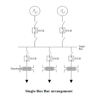
Bus-bars are conductors to which several circuits are connected Bus-bar is either flexible or rigid. Flexible bus-bars are made of ACSR conductors and are supported on strain insulators. Rigid bus-bars are made up of aluminum tubes and are supported on post insulators.
 |
| Single Bus Bar – Electrical Substation Equipment |
6. Earthing Switch
It is a switch which connects a conductor to the earth so as to discharge the charges on the conductor to the earth. Earthing switches are generally installed on the frames of the isolators.
7. Relay
It is an automatic device, which closes its contacts when the actuating quantity/quantities reach a certain predetermined magnitude/phase.
8. Lighting Arrester (Surge Arrester)
The electrical substation equipment connected between the conductor and ground to discharge the excessive voltages to earth. Surge arresters divert the over-voltages to earth and protect the electrical substation equipment from over-voltage surges.
9. Auto-reclosers
Automatic closing of the circuit breaker after auto-reclosers opening. Auto-recloser is provided to restore the service continuity after interrupting transient fault. High voltage circuit breakers used for controlling overhead transmission lines and distance protection scheme for line protection are provided with such a feature.
10. HRC Fuse
High rupturing capacity cartridge fuse is used for over-current protection of low voltage and high voltage circuit.
11. Protective Scheme
A selected set of protective systems which protect one or two components of the power systems against abnormal conditions. Eg: generator protection scheme transformer protection scheme.
12. Structure
Galvanized steel structures are made of bolted/welded structures of angles/channels/pipes. These are used for towers gantries equipment support structures. Galvanized structures provide rigid support to the various equipment and insulators. The design should be safe and economical. Compensating substations are installed at an interval of 300km along EHV – AC lines for feeding reactive power VAR to line.
13. Following Compensation Equipment is Necessary for Voltage Control
- Series capacitors are sometimes installed in series with long EHV AC Transmission lines to compensate line reactance.
- Shunt capacitors are installed near load points in distribution substations receiving substations for improvement of power factor. Shunt capacitors are switched on during high inductive loads. They are switched off during low loads. Shunt capacitors are also included in static Var sources (SVS).
- Shunt Reactors are necessary with long EHV transmission lines to compensate for the reactive power of the line capacitance during low loads.
- Static Var Sources (SVS).These are thyristor controlled shunt capacitors and shunt reactors which give rapid, step less control of reactive power VAR. These are connected in receiving stations and distribution systems.
- Power Line Carrier Current Equipment (PLCC) is necessary for transmitting/receiving high-frequency signals over the power line (transmission line) for the following: Voice communication, data transmission, protection signaling, control signaling.
 |
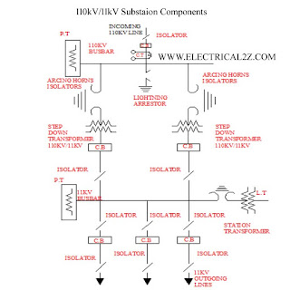
| 110kV/11kV Electrical Substation Equipment |
Electrical Substation Equipment Function
1. Bus-bar: Incoming and outgoing circuits connected bus-bars
2. Circuit-breakers: Automatic switching during normal or abnormal conditions
3. Isolators:( Disconnections) Disconnection under no-load condition for safety isolation and maintenance
4. Earthing switch: To discharge the voltage on dead lines to earth
5. Current Transformer: To step-down currents for measurement control and protection
6. Voltage Transformer: To step down currents for measurement control and protection
7. Lighting Arrester (surge arrester): To discharge lightning over voltages an switching over voltages to earth.
8. Shunt Reactor: To provide reactive power compensation during low loads
9. Series Reactors: To reduce the short circuit current or starting currents.
10. Neutral-Grounding Resistor: To limit the earth fault current.
11. Coupling capacitor: To provide connection between high voltage line and power line carrier current equipment.
12. Line trap: To prevent high frequency signals from entering other zones.
13. Shunt capacitors: To provide compensations to reactive loads of lagging power factors
14. Power Transformer: To step-up or step-down the voltage and transfer power from one ac voltage to another ac voltage at the same frequency.
15. Series Capacitors: Compensation of long lines.
Now-a-days, generation and transmission is almost exclusively three-phase. The secondary transmission is also 3-phase whereas the distribution to the ultimate customer may be 3-phase or single-phase depending upon the requirements of the customers.
C.S. represents the central station where power is generated by 3-phase alternators at 6.6 or 11 or 13.2 or even 33 kV. The voltage is then stepped up by suitable 3-phase transformers for transmission purposes. Taking the generated voltage as 11 kV, the 3-phase transformers step it up to 132 kV as shown. Primary or high-voltage transmission is carried out at 132 kV.
The three phase, three wire overhead high voltage transmission line next terminates in step down transformers in a electrical substation known as Receiving Station (R.S.) which usually lies at the outskirts of a city because it is not safe to bring high-voltage overhead transmission lines into thickly populated areas. So, the voltage is stepped down to 33 kV.
From the Receiving Station, power is next transmitted at 33 kV by underground cables or by overhead lines to various sub-stations (S S) located at various strategic points in the city. This is known as secondary or low-voltage transmission. From now on wards starts the primary and secondary distribution. At the sub-station (S S) voltage is reduced from 33kV to 3.3kV 3-wire for primary distribution.
Consumers whose demands exceed 50 kVA are usually supplied from SS by special 3.3 kV feeders. The secondary distribution is done at 400/230 V for which purpose voltage is reduced from 3 .3kV to 400 V at the distribution sub-stations. Feeders radiating from distribution sub-station supply power to distribution networks in their respective areas. The most common system for secondary distribution is 400/230V, three phase four wire system. The single phase building lighting load is connected between any one line and the neutral.
Hope you understand this article about the 13 Important Electrical Substation Equipment. In case of any doubt please comment below. Please follow our website for future updates. Thank you for visiting our website @ElectricianWorld.Net

It’s a cool article… bro