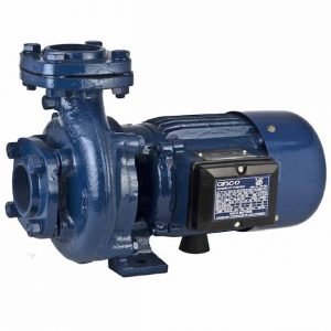
Preventive Maintenance of Electric Motor | Points to be attend during periodical maintenance: general cleaning and blowing off of dust with compressed air at a pressure of 80 to 100 lb. per sq.in.
i. Checking of air gap
ii. Greasing or oiling of bearings
iii. Measurement of insulation resistance of windings
iv. Attention to slip ring or commutators
v. Checking up of carbon brushes and brush gear
vi. Checking current taken by motor
vii. Checking tightness of terminal connections
viii. Checking if motor is operating smoothly and without vibration.
N.B. whenever any motor is inspected, it is equally important to check the starter and control gear.
Table of Contents
Air Gap Measurement – Preventive Maintenance of Electric Motor
Air gap depends upon the size of the motor. AC motors have much small air gaps than DC motors. The gap between the rotor and the stator varies from a few mils (thousands of an inch) to 50 miles or more depending upon the size of the motor. The air gap is measured by inserting long steel feeler gauge leaves in the air gap between the rotor and the stator and ascertaining the maximum thickness of the feelers that can passed. At least four readings should take at different points around the periphery of the motor, i.e. top, bottom, front and back. Unless acre is taken in measuring the gap, the results will not be consistent.
When any new motor is installed, air gap readings should be clearly recorded in the motor history sheet and filled for future reference. Later on, if the top air gap is found to be much higher than at the side and the bottom, it clearly shows that the bearing has worn down. Belt-driven machines usually show greater wear on one side than on the other. Several manufacturers of motor provide suitable holes in the end covers so that a feeler-gauge may be inserted for measuring the air gap.
Precautions in Fitting Bearings
Ball & Roller Bearings Usage
Ball and roller bearing are manufactured to very close tolerances and are therefore easily damaged by careless handling and fitting. Therefore, utmost care is required in fitting up and maintaining them.
The following points require special attention:
a. The bearing housing and the shaft end, over which the bearing fits, should be thoroughly cleaned so that the bearing fits neatly and just push tight. Bearings should never be driven tight, because it will distort the race and damage the bearing. Therefore, the fitting surfaces should be carefully checked and any burs or surface injuries should be cleaned up with a smooth file and finished with fine emery where necessary.
b. Scrupulous cleanliness is essential in handling ball and roller bearings. Grit and dirt are enemies to all bearings. Stored bearing should not be removed from their boxes until they are required for fitting and only clean white cotton fluff less cloth (never cotton waste) should be used in their vicinity.
c. When fitting new bearing, the protecting oil put in by the manufacture need not be washed off as it makes a good lubrication for the first few hours of running. Grease, of the best quality, should be lightly packed into the bearing itself and the bearing then fitted into position in its housing. The inner race may be pressed on to the shaft but if this not practicable; it can be fitted into position by lightly tapping with a wooden mallet over a tube passing over the shaft end. If a tube is not available, a copper drift may be used. Care must be taken to ensure that the bearing is square on the shaft. Wooden blocks should not be used unless they are of very hard wood and show no tendency to splinter done. In handling ball or roller bearing, avoid dust and grit as plague.
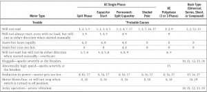
Bearing Problems
Alignment of Directly Coupled Motors
The alignment is easily checked by laying the edge of a steel foot rule against the sides of the two flanges and checking whether the steel edge bears fully against the sides of the two flanges or if there is any gap. The gap can be readily seen if a light is placed on the opposite side. Any variation in levels is corrected by suitable steel shims. The alignment should not only be correct in the vertical and horizontal planes but the axis of both the shafts should be in the same line and not make an angle with each other. This can be checked by measuring the gap between the flange faces at four points, i.e. top, bottom, front, and back.
Static and dynamic balancing of motors
Balancing
However carefully constructed, a motor armature shaft has necessarily some unequal distribution of weights in its body, which results in its axis of gravity being slightly off centre and out of line with the axis of rotation. Therefore, when the armature rotates, centrifugal force is created which act upon bearings. This causes the whole machine to vibrate.
Its intensity varies at different speeds and becomes maximum at some critical speeds due to the effects of resonance. The amount of unbalance determines the degree of vibration. For smooth running and long useful life, the rotating parts should be properly balanced. Then the machine will run smoothly without producing any oscillation, vibration or noise.
Balancing consists of re-adjusting the distribution of masses in the body in such a way as to bring the axis of gravity to coincide with the axis of rotation. This is done by placing a counter-weight on or removing some weight from some part of the armature in such a way that the unbalanced centrifugal force is cancelled out. To do this is necessary to determine precisely where the counter-weight is to be placed or removed, and what the weight should be.
Static Balancing
In static balancing, the rotor is supported on a pair of perfectly horizontal knife edges. If the armature is in perfect balance, the rotor should rest in any position. If, on the other hand, the rotor is not well-balanced and has uneven distribution of weight, the rotor will turn round and come to rest with the heaviest portion in the lowest position, and the hollow over portion will occupy the top position.
After noting the lowest point of the armature, small counter-weight should be fixed on the top part of the armature and a test conducted again. The operation should be repeated until the rotor can come to rest equally well in all positions. The amount of weight added and its location has to be found by the trial and error method, remembering that the greater the distance from the centre, the smaller should be the weight. An alternative method is to remove some weight from the heavier portion of the rotor by drilling a hole in the end supports or by chipping as found convenient.
 |
| Preventive Maintenance of Electric Motor |
Dynamic Balancing
This means carrying out the balancing operation when the rotor is actually rotating. Although a body may appear well-balanced by the static rest, any little residual balance becomes prominent at high speeds. Special dynamic balancing machines are available by means of which the exact amount of weight to be added as well as its location can be accurately determine. The rotor is mounted on a pair of pedestals carrying spring suspension systems, and driven at any speed required. The machine incorporates a visual indicator which amplifies the vibration felt on the bearings due to the unbalance of the rotor.
A suitable device is also incorporated by means of which a counter-weight of the right value may be temporarily inserted at the right place on the same shaft to which the armature is coupled, until all oscillations are neutralized. After the weight of the counter-weight, the correct radial length and angle of location are determined, the armature is removed and a permanent counter-weight fixed at the correct point, and a test conducted once again to confirm the correction. When balanced in this way, the armature will run very smoothly at all speeds without any trace of vibration. Care must be taken in securing the counter-weights properly so that they do not fly off at high speeds.
For balancing large armatures which may not permit of being moved and placed on the balancing machine, special electronic equipment has been developed making use of vibration detectors and cathode ray oscilloscopes, so that the balancing operation may be performed in ‘situ’ on the machine itself.
Final Word
Hope you understand this article about the Preventive Maintenance of Electric Motor. Incase of any doubt please comment below. Subscribe our website to get every new post update to your email. Please follow our website @ElectricianWorld.Net for future updates. Thank you for visiting our website.