Operation and Maintenance Of Electric Motor | The article is completely covered about an electric motor operation and maintenance. so, read carefully without skip any paragraph.
Table of Contents
Change the direction of rotation
By interchanging any two of the three main supply leads to the stator. No change is required for the rotor leads in slip ring motors.
Role of single phase preventer
The usual magnetic overload releases provided, only act at 500 per cent above full load current, as they have to cater for the heavy starting kick. They are primarily intended as a protection against short circuits.
They will not operate at lower overloads of 30 per cent to 50 per cent as when single phasing. Moreover, dashpot type overload releases do not often function correctly at the currents to which they are set. Thermal overload releases are effective if properly working on nearly full load.
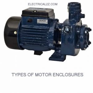
Types of Enclosures
There are six types enclosures are commonly used on the motors.
Permissible Overloads
After having attained the temperature rise corresponding to continuous run on full load, a generator should be capable of withstanding 50% overload for 15 seconds; motors shall be capable of withstanding the following excess torque: (ISS: 325 – 1959, BSS: 2613 – 1957).
Up to 50 hp – 100% for 15 seconds
Above 50 hp – 75% for 15 seconds
Above 500 hp – 60% for 15 seconds
Motor with short term rating – 100% for 15 Seconds
The old Indian standard specifications provided for an overload capacity of
25 percent for ¼ hour upto 4 hp
25 percent for ½ hour upto 10 hp
25 percent for 2 hours above 10 hp
The main point that determines the rating is the maximum temperature permissible in the motor windings. Naturally, it depends upon two factors.
i. The ambient temperature which decides the amount of heat that the motor can dissipate
ii. The class of insulation, employed for the motor windings
Effect of ambient temperature
Ambient which determines the rating of all electrical equipment temperature is the temperature of the surrounding air in which electrical equipment works. It is a very important factor The life of any electrical equipment like a motor, generator, transformer, etc., is directly dependent upon the heat stresses to which the insulation is subjected to in operation, i.e., the maximum temperature permitted in the windings.
The limits of temperature for different classes of insulation employed are given in (Table 1 column no 3). These limits have been specified to ensure a life of about 25 years while the life will not be increased very much more if a lower temperature is adopted, it will fall rapidly, if these temperature limits are exceeded.
The temperature of inner most layer of the insulation depends upon:
a) The amount of heat produced
This is equal to I2RT, i.e., The square of the current multiplied by the resistance of the windings and the time in addition there are also eddy current and hysteresis losses in the core .
b) The amount of heat dissipated
Heat is dissipated in two ways, by radiation and by convection, radiation is dependent upon the surface area exposed (cooling fins are often added on the body to increase this) and the ambient temperature of the atmosphere in which the equipment is working. The heat lost by convection is naturally related to the amount of air passed through the machine by the ventilating fans mounted on the rotor, and the temperature of the air as it enters the machine (ambient temperature). To ensure quicker dissipation the thickness of the windings is also kept low and air space is and ducts are provides wherever possible.
The ultimate temperature of the windings is a balance between the heat produced and heat dissipated.
Insulation classification
There are four classes of insulation employed for windings as shown under:
|
Class
|
Material
|
Ambient Temperature
|
Maximum Temperature
|
Maximum Temperature permissible by thermistor
|
|
|
|
|
|
|
oC
|
oF
|
|
O
|
Cotton, silk, paper, etc. when not impregnated or immersed in oil
|
40oC
|
25oC
|
65o
|
149o
|
|
A
|
Cotton, silk, paper, etc. when impregnated or immersed in oil, enameled wire
|
40oC
|
50oC
|
90o
|
194o
|
|
B
|
Mica, asbestos, glass, wool, etc. in built up form
combined with binding cement
|
40oC
|
70oC
|
110o
|
230o
|
|
C
|
Porcelain, pure, mica, etc.
|
|
Not Specified
|
|
|
The above table does not apply to traction motors. It will be observed that temperature rise for class O is 15oC less than for class A. and for Class B it is 20oC more than for class A.
Every insulation material starts deteriorating if its temperature exceeds the above values. The temperature rise therefore puts a limit on the power which we can get out of a machine safely and therefore determines the rating of the machine.
Overloading a motor beyond its capacity may no doubt enable one to tide over a crisis, but if resorted to frequently will seriously reduce the life of the equipment.
When the permissible rise in temperature is specified as 40oC for motor winding, normally it refers to the rise above the standard ambient temperature of 40oC. the actual temperature of the motor winding, with class A insulation thus can rise up to 90oC. If the ambient temperature is lower, say 30oC as in a cold climate, the permissible temperature rise is naturally higher, i.e. 90-30=60oC. The temperature limit is still 90oC as before. A motor can thus stand a higher amount of load when working in an cooler atmosphere than otherwise.
In tropical countries like India, where the ambient temperature in summer may go up as high as 113oF, i.e. 45oC the permissible temperature rise can only be 45oC. For continuous operation under such conditions, an ordinary motor will have to be slightly derated. Therefore, in placing orders for a new motor, the ambient temperature of 45oC should preferably be specified.
Function of low-volt release
The low volt release in hand operated starters usually consists of a shunt coil connected across the mains, so arranged that it holds the spring loaded started handle in the ‘on’ position as long as the supply is ‘on’. If the supply should fail while the motor is running or if the voltage drops unduly, the shunt coil is weakened and can no longer released and automatically returns to the starting position and cuts off the supply of the motor. This ensures the motor can only be re-started in the normal manner after the supply is resorted.
If such stuck in the full ‘on’ position, it will create an undesirable condition, i.e. full voltage will be applied to the motor terminals without any starting resistance, when the supply gets resorted. This may not only damage the motor, but it may also result in the tripping of the incoming feeder to the shop. In a contactor type starter, every contactor is inherently a no-volt release as it opens automatically if the supply voltage falls unduly.
Function of overload release
Overload releases are intended to protect the motor against overloads. All overload devices make use of the current through the motor circuit to lift off a contact in the low-volt coil circuit or make a contact in the trip circuit or mechanically operate the trip bar, thus shutting down the motor in the event of excessive overload. There are mainly two types:
Magnetic overload releases: These are usually of the instantaneous type and are intended to protect the motor against internal short-circuits, bearing seizing and rotor getting locked. Alternatively, they may be of the solenoid operated plunger type fitted with dashpots as protection against heavy overloads.
Thermal overload release, which protect the motor against sustained overloads. Whatever may be the type, starters are provided with a reset button or handle, which makes it obligatory for a trained electrician to visit the spot, investigate the cause of the tripping and reset the trip. Until the reset device is operated, the motor cannot be started.
Function of thermal overload release
A thermal overload release is one, in which the heat produced by the excessive overload current is made use of to trip the motor circuit. Several designs of thermal overload releases have been developed by different manufacturers, but are generally based on one of the following principles:
Deflection of a bimetallic strip due to the heat caused by the motor current, which may pass either directly through the bimetal or indirectly through a separate heater provided below the bimetallic strip. This deflection of the bimetallic strip releases the trip bar. The bimetallic strip is made up of two dissimilar metals, having different coefficients of expansion. When such a strip is heated, it bends due to the unequal expansion of the two metals and this bending action is used to trip the overload contacts.
Rotation of a spring loaded plug due to the softening of the solder by the heat produced by the motor current, when passing through a heater which surrounds the soldered plug. This operates the trip contacts. In a 3-phase motor, 3 thermal elements are provided, one for each phase winding.
A common trip bar is provided to open the control circuit if any of the overload elements operate. Each of the thermal elements is provided with an adjustment for setting the degree of overload at which it should operate. A thermal overload release is superior to the magnetic overload release in the protection it gives to the motor against sustained overloads since it takes into account the actual heating effect of the motor windings due to the overload. No magnetic overload release can fulfill such a requirement as it depends entirely upon the value of the current and does not take into account the important element of time.
As already known, fuses and magnetic overload releases are ineffective and unsatisfactory for affording any protection against the overloading of motor, since they should be able to withstand the heavy rush of current during the starting period. Thermal overload, on the other hand, protects the motor against sustained overloads, as its thermal characteristic very closely resembles that of the motor winding and, therefore, it trips the circuits just when the motor windings become unduly hot and can no longer bear any further rise in temperature. Fig shows the characteristic curve for a thermal overload release.
A combination of a magnetic element with an instantaneous trip against short circuits and a thermal element which takes care of sustained overloads, would together gibe complete protection to a motor.
Interlocks
Interlocks are devices provided on equipment to prevent their being operated incorrectly. They may be either mechanical or electrical in action. Some examples of interlocks are given below:
The starter cover is mechanically interlocked with the main control switch so that the cover cannot be opened until the main switch is off. It also ensures that the main switch cannot be closed until the starter cover is put back. This makes it impossible for staff to work inadvertently on live equipment.
In automatic contactor type starters, electrical interlocks are provided to ensure the correct sequence of operation. Mechanical interlocks are provided on the star and delta contactors so that they can never both be simultaneously on.
In slip ring motors, an electrical interlocking contact is provided on the rotor short circuiting switch to ensure that it is opened and the starter handle returned to the start position before the slip ring motor is started. Similar interlocks are also usually provided for air-compressor motors, to ensure that the compressor is unloaded before the motor is started, to reduce the starting current.
Indicating and protecting devices for large size motors
Indicating devices
The most common and useful indicator on a starter is an ammeter, especially if the full load current is marked on the dial in red. This furnishes a ready check on the operation of the motor. Some starters are provided with ‘on’ and ‘off’ flag indications and some with flag indication to show up if any protective device has operated. A voltmeter would also be a useful addition.
If overload mechanism trips frequently what action to be taken
If an overload trips occasionally, it is indeed a good sign, as it proves that the mechanism is functioning properly. If the mechanism has never operated, it is by no means an indication of good maintenance. On the other hand, it is time that its operation is thoroughly checked. If, however, the tripping is frequent, check if the machine is overloaded, by inserting an ammeter and measuring the current in each of the phases. If working currents in each of the phase s are equal and less than the full load current, check if the proper grade of oil has been used in the dashpots and if the mechanism is in good operating condition. If they are both o.k.,
Raise the overload setting slightly as the calibration plate may not be quite correct. Keep the equipment under observation.
If a hand operated starter trips frequently when starting, it may be due to the starter handle being moved too rapidly from one step to the next without allowing sufficient time for the motor to accelerate, some training is required before any one learns the proper operation of manually operated starters. A good rule is to watch the ammeter reading and ammeter needle has dropped down sufficiently. If the motor is nearby, the sound of the motor also shows if it has attained the maximum speed corresponding to the notch. In automatic type starter, current relays are provided to ensure sufficient time to elapse from one step to another. If they are defective or wrongly set, the overloads would naturally trip frequently.
There are so many types of control devices are used in the motors. And that it is impossible to mention all of them. The following are just a few examples, 1. Mechanically operated switches, 2. Electrically operated switches, 3.Pressure operated diaphragm switches, 4. Thermostats operation on a variation of temperature, 5. Photo electric relay and 6. Electronic relays
Role of relays in motor:
Relays are extensively used for a variety of purposes and several designs have been evolved to suit different needs.
Relay can be connected to any control device desired and in turn, operate very much heavier equipment. For instance, a control device of a few milliamps is sufficient to operate a low voltage relay, whose contacts in turn can operate a heavy contactor which could switch on and off a large amount of power or high voltage equipment at point far away. This is illustrated in fig. This shows a remote controlled pumping installation.
If the control device is a float switch fixed on an overhead storage tank, a few milliamps in the relay circuit is sufficient to start and stop a large motor driven pump, may be of 100 h.p., automatically even if situated several miles away, depending only upon the fall or rise of water level in the tank.
Periodical maintenance
General cleaning and blowing off of dust with compressed air at a pressure of 80 to 100 lb. per
sq.in.
i. Air gap checking
ii. Bearings oiling
iii. Winding insulation resistance measurement.
iv. slip ring or commutators
v. Brush gear checking
vi. Current taken by motor
vii. Tightness of terminal connections
viii. motor is operating smoothly and without vibration.
Causes of low insulation resistance and rectification of low insulation resistance
Read this article of causes and rectification of low insulation resistance windings completely.
 |
| Operation And Maintenance Of Electric Motor 1.1 |
Steps to be taken when the motor is unduly hot
The following steps should be taken:
- Feel the motor body and the bearings to know whether they are really hot. Quite often reports are false. If they are abnormally hot, switch off the supply. Look for any smell of burnt-out insulation and ascertain if there has been any smoke from the motor.
- If it is a 3-phase motor, check if the motor is single phasing by any chance, i.e. examine if any one of the fuses have blown out. Check also whether the full voltage is available at the motor terminals on all the phases.
- Check also if the motor is overloaded by noting the line current taken by each phase of the motor. If the current is excessive on all the phases, the load on the machine should be reduced. At the same time, the starter overload releases should be inspected to see whether the overload setting is right and if it is right why the overload did not trip. Reset if required.
- Check the supply voltage. If the voltage is low the motor will draw more than its rated current, for the same load.
- Inequality of current in the 3-phases may be caused by inequality of the supply voltage due to fault on the supply system or large single phase loads on a 3-phase system. It may also be due to a bad joint on the overhead lines or a bad contact, i.e. one which is overheated, burnt out, worn out, strongly shaped or adjusted, either on the main switch or in the starter. It could also be due to a blown fuse on one supply line.
- If the currents, on all the 3-phases are equal and normal and yet there is overheating and smell of burnt insulation, check air gap to see whether the rotor is touching the stator anywhere or there is any other mechanical defect.
- If everything is O.K., then it may be due to an internal fault inside the windings or from a winding to the earth. Open out and examine the windings for signs of overheating and measure the ohm resistance of each winding.
- If the windings and air gap are alright, check whether the ventilating ducts are clogged up preventing free circulation of air. Of course, you should also make sure that the ventilating fan is existing on the armature.
In DC motors, look for signs of flashover on the commutator and take appropriate action.
Vacuum impregnation
Vacuum impregnation is very similar to the hot dip method but is much more efficient. In the hot dip method, one cannot be sure if all the air spaces inside the winding are fully impregnated with the varnish. In vacuum impregnation, all air is first removed out, which ensures that the insulating varnish gets sucked in into the innermost recesses. If the subsequent baking is thorough, there will be no possibility of entry of humid air from outside into the winding and, therefore, the winding is fully protected and will give a long and trouble-free service. The impregnation plant consists of a large air-tight double-jacketed vacuum impregnation chamber A (fig.) with a removable lid B.
- The interior of the tank can be heated up by circulating steam or hot oil through the jacket. The insulating varnish which should be of the baking type is kept stored in another storage tank C. A motor driven compressor-cum-vacuum exhauster is provided with suitable valves to create either vacuum or pressure of 20 to 30 lb. per sq in. in tank A as required. The various steps in impregnating an armature are as follows:
- Remove the top cover and place the armature inside the tank. Close the top cover and heat up the chamber A to 100oC for at least 2 to 4 hours by circulating steam or hot oil through the jacket. During this period, the air inside the tank is pumped out and vacuum is maintained. By this means, all the air and moisture inside the coil is completely driven out since all liquids vaporized very rapidly in vacuum even without applications of heat.
- Now allow insulating varnish by opening the sluice valve to flow into the chamber A, until the armature is fully immersed. Note that at no time is air allowed in contact with the windings.
- Apply an air pressure of 20 to 30 lb into the space above the varnish level in tank A, after closing the varnish outlet vale. The varnish will now be forced by pressure into all the porous spaces in the interior of the coil.
- After ½ an hour, allow all the varnish to flow back into the storage tank C under air pressure and the excess varnish in the coil to drain out.
- Bake the armature for 4 to 8 hours at a temperature of 100oC to 110oC. This will cause the varnish in all portions of the coil to set and become bone dry. Never exceed 110oC in any circumstances as it will endanger the insulation.
- If the operation is carried out by trained staff, a first class job can be done and the coil can be confidently expected to give excellent service for long periods.
The baking operation should be thorough. Half baked windings are useless and will give a lot of trouble. In fact, hand varnishing is certainly much better than half-baked vacuum impregnation. Remember that the heat should penetrate and bake the varnish in the innermost recesses of the winding and this takes several hours.
Insulation varnishes are marketed under several trade names such as Ohmaline, Armacell, Esbalite, Synobel, etc. and they are available in two forms, i.e. ‘air drying’ for hand application and ‘baking’ type for hardening inside hot ovens. Suitable thinners are also available to dilute the varnish if it becomes too thick.
Final Word
Hope you understand this article about the Operation And Maintenance Of Electric Motor. Incase of any doubt please comment below. Subscribe our website to get every new post update to your email. Please follow our website @ElectricianWorld.Net for future updates. Thank you for visiting our website.